From the Space Race to Mars
Lunar exploration has been one of humanity's most ambitious endeavors since the Cold War. Understanding where we've been, and what we learned, explains why this MQP exists and why power is the critical problem to solve.
The Race & the Landings
Discovery, Absence & Return
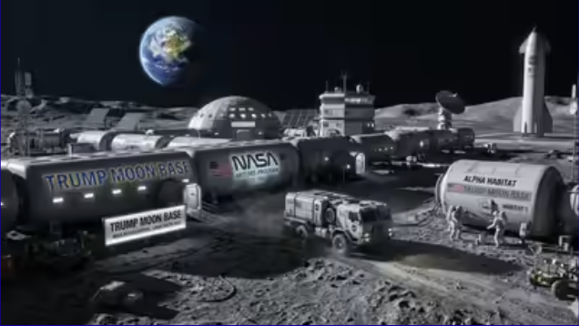
Humanity's Return to the Moon
NASA's Artemis program is the most ambitious crewed lunar effort since Apollo. Unlike Apollo, which was about planting a flag and winning a race, Artemis is about building a permanent infrastructure for long-term human presence on and around the Moon.
An uncrewed test flight of NASA's Space Launch System (SLS) and Orion capsule , the hardware that will take astronauts back to the Moon.
Orion traveled 434,522 km from Earth, farther than any crew-rated spacecraft in history. It successfully entered and exited lunar orbit and splashed down in the Pacific. All systems were validated for crewed flight.
The first crewed lunar flyby since Apollo 17 in 1972. Four astronauts, Reid Wiseman, Victor Glover, Christina Koch, and Jeremy Hansen, flew around the Moon without landing, validating life support systems and crew operations for the first time in a lunar environment.
Victor Glover became the first Black astronaut to fly to the Moon. Jeremy Hansen became the first Canadian to leave Earth orbit. This mission closed a 50-year gap in human lunar exploration.
The first crewed lunar landing since December 1972. Astronauts will descend to the lunar south pole using SpaceX Starship as the Human Landing System (HLS). The first woman and first person of color will walk on the Moon.
Later Artemis missions aim to build a permanent Artemis Base Camp and the Lunar Gateway space station in lunar orbit, making the Moon a permanent outpost for humanity.
Location, Ice, and Power Requirements
Every aspect of the lunar power plant design is influenced by its intended location. NASA has designated the lunar south pole as the destination for Artemis, and for good reason. Understanding why explains many of the design choices in this MQP.
Permanently Shadowed Regions (PSRs)
The Moon's axial tilt is only 1.54°, nearly perfectly upright relative to its orbit. This means the floors of deep craters near the poles never see sunlight. Some of these Permanently Shadowed Regions (PSRs) haven't seen sunlight in over two billion years. Their floors sit at a near-constant −230°C, colder than the surface of Pluto, making them the coldest stable locations in our entire solar system.
That extreme cold is exactly why they're so valuable: over billions of years, comets and asteroids have delivered water ice and other volatiles to the Moon's surface. Most evaporated in sunlight, but those that landed in PSRs have remained frozen ever since. The LCROSS impact in 2009 confirmed that water ice is present in Cabeus crater in concentrations of 5–10% by mass.
Shackleton Crater
The prime candidate for Artemis Base Camp sits near the rim of Shackleton Crater , a 21-km-wide, 4-km-deep crater essentially sitting on the south pole itself. The crater's rim has a remarkable property: because the Moon barely tilts, the rim peaks stay partially illuminated by low-angle sunlight for about 89% of the year. NASA has identified this area as one of the best places for a long-duration lunar outpost.
The geometry is almost perfect: the base camp sits on a sunlit ridge, while the PSR floor just a few kilometers away holds the water ice needed for In-Situ Resource Utilization (ISRU).
The Case for Nuclear Power at the South Pole
Even with 89% sunlight on Shackleton's rim, solar panels fail completely during the 11% of time that's dark, and those dark periods can last days. At the south pole, the Sun never rises high; it skims the horizon at 1–2° elevation, creating extremely long shadows and making solar panel positioning complex. A nuclear reactor solves all of this: it doesn't care whether the Sun is up, where shadows fall, or what time of day it is. It delivers the same 150 kWe in perpetuity.
The reactor would ideally be positioned at least 1 km from the crew habitat, far enough that the radiation dose to crew remains within acceptable limits, but close enough that power transmission losses are manageable. Shielding mass can be dramatically reduced by leveraging shadow shielding , putting the reactor over a terrain rise so that the lunar landscape itself blocks the radiation.
What Does 150 kWe Power?
150 kilowatts is a substantial amount of electrical power, roughly equivalent to 50–60 American homes. But on the Moon, the needs are very different from a suburban neighborhood. There's no grid to draw backup power from, no maintenance crews on standby, and no hardware stores. Everything has to work, all the time, from a single power source.
The breakdown below estimates how 150 kWe might be allocated across a crewed outpost. The exact numbers depend on outpost size and mission goals, but the proportions reflect current NASA planning assumptions. ISRU dominates, it's the whole reason for being at the south pole in the first place.
Importantly, this power must be available continuously. Life support cannot be paused for a recharge cycle. The reactor doesn't sleep. That's the fundamental requirement driving this entire project.
Through every lunar night · For years at a time
Design Goals
With the context above established, the MQP team defined six specific objectives that the power system design must satisfy.
Deliver 150 kWe Continuously
Net 150 kWe of electrical output at all times, no degradation through lunar night, no interruption for maintenance, sustained for the full mission lifetime.
Autonomous, Self-Contained
The system must operate autonomously , monitoring its own health, managing reactor power, and handling anomalies without requiring crew intervention or real-time ground control.
No On-Site Assembly
The system must land as a single integrated unit and deploy itself. This drives the use of deployable radiators and means every connection, seal, and mechanical joint must work correctly after surviving launch, transit, and landing loads.
Survive Lunar Extremes
Hard vacuum, 300°C thermal swings, reactor and cosmic radiation, and abrasive charged regolith dust , all over a multi-year mission lifetime. Every material and component selection must account for the full environmental envelope.
Fit Realistic Deployment Constraints
System mass and stowed dimensions must be compatible with near-term lunar landers. At roughly $1M per kilogram to the lunar surface, every gram matters. The design must maximize specific power (W/kg).
Evaluate the TAC
A core research objective was to evaluate the Turbo Alternator Compressor (TAC) as the power conversion unit within a Closed Brayton Cycle at the 150 kWe scale.
How We Approached the Problem
Three complementary methods were used to evaluate whether this system concept is feasible and to characterize its thermal performance.
Thermodynamic Cycle Analysis
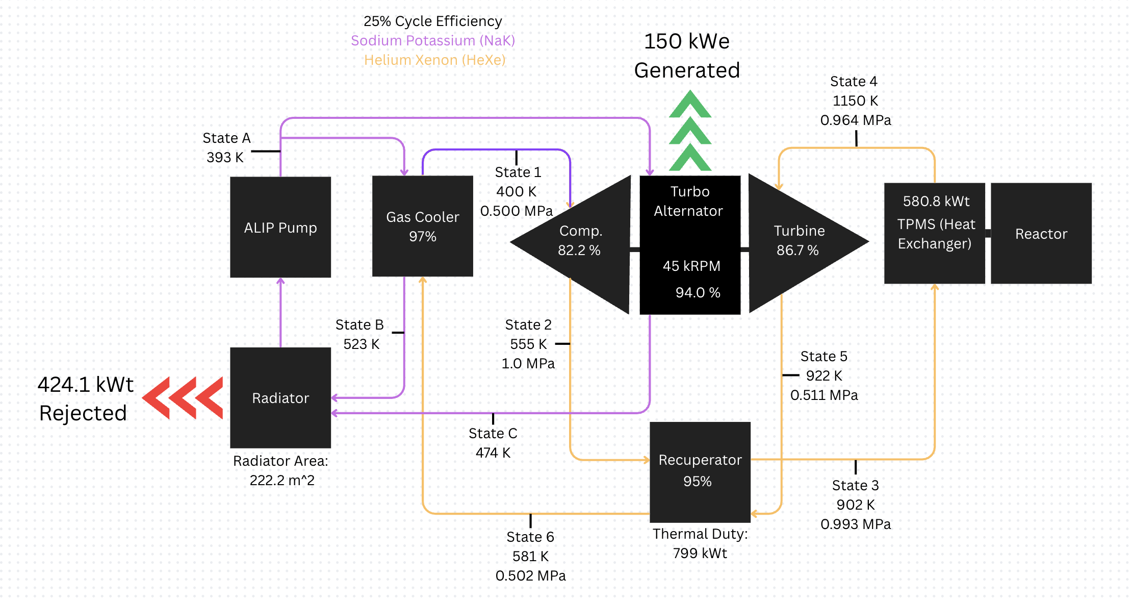
A full analytical model of the Closed Brayton Cycle was developed using thermodynamic first principles. The team applied the First and Second Laws of Thermodynamics to find the cycle parameters, turbine inlet temperature, pressure ratio, and recuperator effectiveness , that maximize electrical output given the SAFE-400's thermal constraints.
The analysis confirmed that a well-designed CBC with He-Xe working fluid can achieve ~25% conversion efficiency, producing 150 kWe from the reactor's 600 kWt thermal output.
Thermal Modeling in SolidWorks
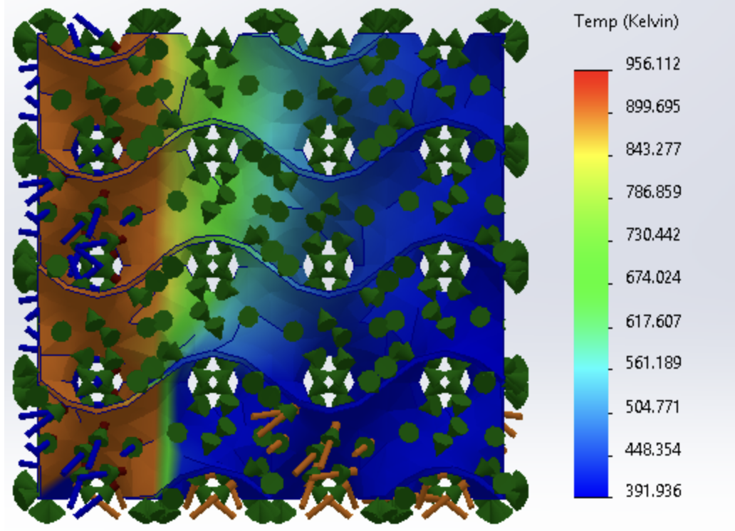
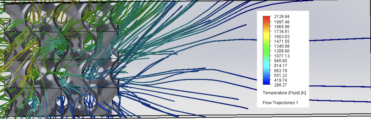
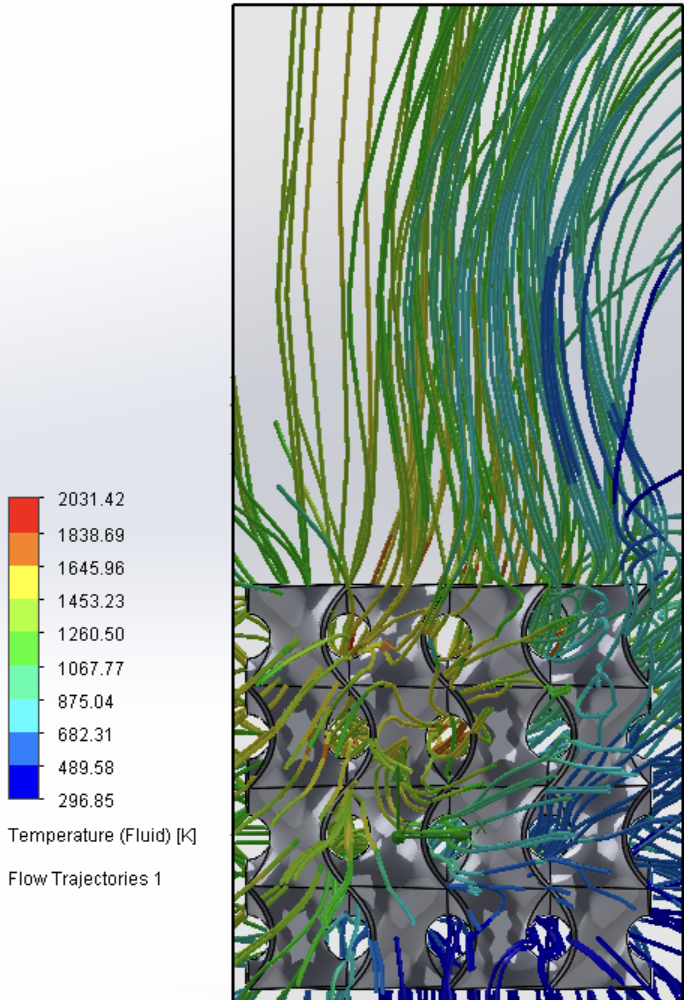
SolidWorks FEA simulation was used to model the thermal performance of a TPMS heat exchanger design. TPMS (Triply Periodic Minimal Surface) structures use complex, mathematically-defined geometries with extremely high surface area per unit volume.
The simulation demonstrated that a TPMS-based heat exchanger provides strong thermal exchange behavior in this application, validating the design approach and informing the thermal sizing of the radiator system. The TPMS geometry also has potential for additive manufacturing, which aligns well with future in-space manufacturing goals.
System-Level Feasibility Assessment
Beyond individual component analysis, the team assessed the complete system, evaluating whether all subsystems can physically coexist within the constraints of a real lunar lander and deployment scenario. This included mass budgeting, volume envelopes, and identifying which subsystem interactions drive the design.
The assessment concluded that the system concept is conceptually feasible , no show-stopping physics violations or engineering impossibilities were found, while clearly identifying thermal rejection as the dominant challenge requiring more detailed future work.
Why Building This Is Hard
The concept is straightforward: put a nuclear reactor on the Moon, convert its heat to electricity, and power a base. The engineering is anything but. Every step runs into obstacles that don't exist on Earth.
Rejecting 424 kW of Waste Heat With No Atmosphere
This is the single hardest problem. On Earth, power plants dump waste heat into rivers, lakes, or the atmosphere. On the Moon there is no air and no water , the only way to shed heat is thermal radiation from large panels pointed at deep space. The system's radiators need roughly 222 m² of panel area , about the size of a tennis court , to continuously shed 424 kW. Those panels must be lightweight, must survive launch, and must deploy automatically on the lunar surface without crew assistance.
Lunar Dust Destroying Everything
Lunar dust is unlike anything on Earth. Apollo astronauts found it coated their suits, jammed mechanisms, and scratched visors within hours. The particles are microscopically sharp (never smoothed by water or wind erosion) and electrostatically charged, making them cling to every surface. A thin layer of dust on a radiator panel reduces its emissivity , its ability to radiate heat , and there's currently no reliable way to clean panels remotely over a multi-year mission. This is an unsolved problem.
300°C Thermal Swings Cracking Everything Apart
The lunar surface swings between +127°C in direct sunlight and −173°C in shadow. The reactor itself runs at around 1,000 K. Every time the system cycles through these temperatures, metal components expand and contract. Over hundreds of thousands of cycles across a multi-year mission, this thermal fatigue can crack seals, delaminate coatings, loosen joints, and fracture welds , with no crew available to repair them. Every material choice must account for the full thermal envelope over years of continuous operation.
Radiation: Shielding Mass vs. Launch Cost
The reactor produces intense neutron and gamma radiation. Crew can't live anywhere near it without adequate shielding , but shielding is heavy, and every kilogram costs roughly $1M to deliver to the lunar surface. The design uses shadow shielding , positioning the reactor behind terrain features so that the Moon itself blocks radiation , but this requires precise placement during landing and limits where the reactor can be deployed.
Everything Must Deploy Itself , Flawlessly
The entire power system must launch folded inside a rocket fairing, land on the Moon, and unfold its radiators automatically , without any crew present and without the ability to send someone to fix it if something goes wrong. Every hinge, latch, motor, cable, and seal must work correctly after surviving the vibration of launch, the thermal shock of transit, and the impact of landing. A single failed deployment means the base has no power. There are no second chances.
Running for Years With No Maintenance
Earth power plants have maintenance crews, spare parts warehouses, and the ability to shut down for repairs. A lunar nuclear reactor has none of these. The TAC spins at 45,000 RPM in a hard vacuum , its bearings must survive for years without lubrication (conventional lubricants outgas and evaporate in vacuum). The reactor must autonomously monitor its own health, manage its own power output, and respond to anomalies without waiting for instructions from Earth, where a signal takes 1.3 seconds one-way.
Micrometeorite Impacts on Radiator Panels
With no atmosphere to burn up incoming particles, the Moon's surface receives a constant low-level bombardment of tiny high-velocity impactors. Radiator panels , which must be large and thin to minimize mass while maximizing surface area , are particularly vulnerable. A single puncture in a fluid-cooled panel could cause coolant loss and cascading thermal failure. Mitigations include redundant parallel flow paths, self-sealing materials, and designing for graceful degradation, but none of these have been validated over multi-year lunar timescales.
Nuclear Safety and Launch Regulations
Any nuclear-powered spacecraft must be reviewed and approved by the White House Office of Science and Technology Policy under Presidential Directive NSC-25. The reactor must be designed to remain sub-critical under every conceivable launch accident scenario , impact, fire, immersion in water, dispersal of fuel. The approval and safety verification process alone can take years and adds significant design constraints that compete with performance and mass goals.
How the System Works
The design uses a modified SAFE-400 reactor as the heat source, a Closed Brayton Cycle for power conversion, and an integrated thermal rejection strategy. Four subsystems work together continuously to deliver 150 kWe.

It's not a flaw in the design , it's a law of physics. Any device that converts heat into work is called a heat engine, and all heat engines are fundamentally limited by the Carnot efficiency limit: the maximum possible efficiency equals 1 minus the ratio of the cold temperature to the hot temperature (in Kelvin).
For this system, the reactor runs at roughly 1,000 K and the radiators operate around 400 K. That gives a theoretical maximum efficiency of 1 − 400/1,000 = 60%. The Closed Brayton Cycle achieves 25% in practice , about 63% of the Carnot limit, which is very good for a real engineering system.
The remaining 75% does not disappear , it becomes waste heat that must be continuously rejected. This is the same reason every power plant on Earth (coal, gas, nuclear) also produces enormous amounts of waste heat. On Earth that heat goes into rivers, cooling towers, or the atmosphere. On the Moon, with no air or water, it can only leave as infrared radiation through large deployable panels , which is exactly why heat rejection is the dominant engineering challenge of this design.
Reactor, Brayton/TAC, Heat Rejection, PCAD
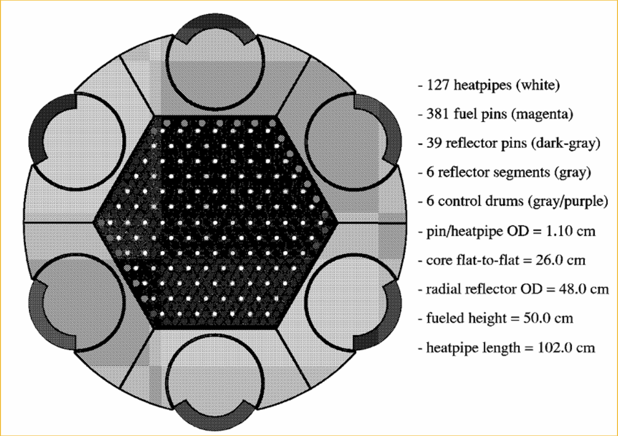
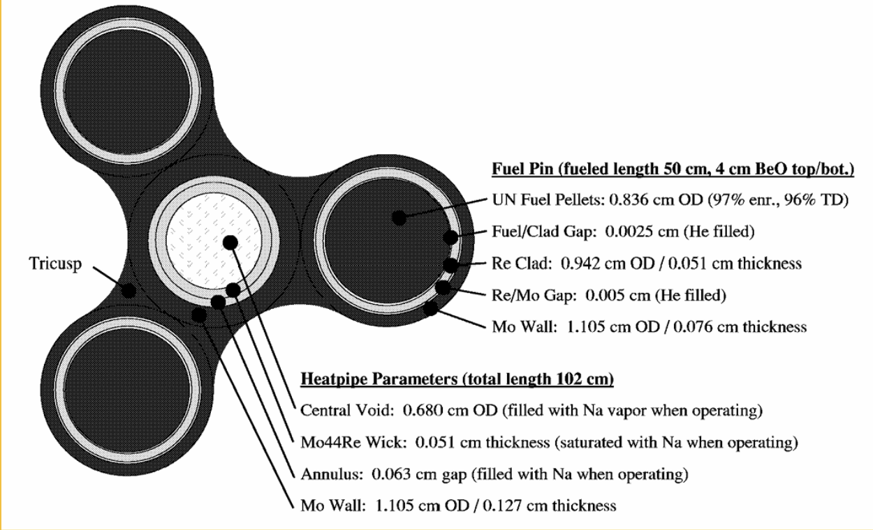
Modified SAFE-400 Reactor
The reactor is based on NASA's SAFE-400 design, a compact, heat-pipe-cooled fission reactor producing 600 kW of thermal power using enriched uranium nitride (UN) fuel. Heat is transferred to the Brayton cycle via liquid sodium heat pipes , entirely passively, with no pumps.
The reactor is launched in a sub-critical state and reaches criticality only after safe landing on the Moon, via remotely actuated control drums. The reactor's small size relative to its power output reflects the extraordinary energy density of nuclear fuel. Uranium nitride's high uranium density and thermal conductivity make it especially well-suited for compact space reactor cores.
Closed Brayton Cycle & the TAC
Three power conversion technologies were evaluated against this design's requirements:
- Closed Brayton Cycle Selected, scalable to 150 kWe, high efficiency (~25%) at SAFE-400 temperatures, space flight heritage from military aircraft and research programs
- Stirling Convertor, high efficiency at small scale, limited scalability above ~10 kWe per unit, suitable for Kilopower-class systems
- Thermoelectric Converter, no moving parts (very reliable), but only 5–8% efficiency, impractical for 150 kWe due to enormous radiator requirements
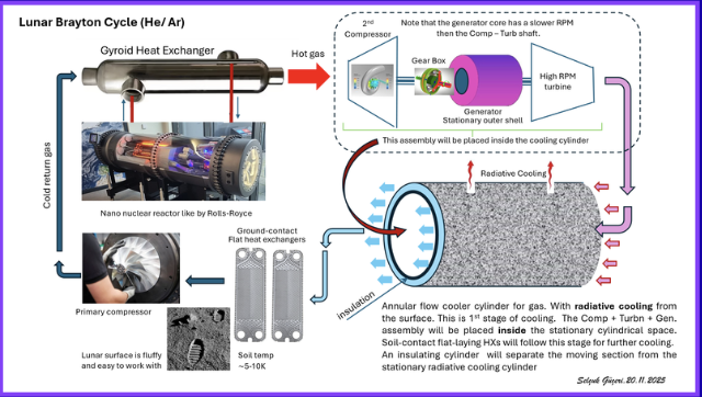
The CBC uses a He-Xe working fluid and a recuperator to pre-heat the compressed gas, significantly boosting efficiency. The heart of the CBC is the TAC (Turbo Alternator Compressor), a single high-speed rotor combining turbine, alternator, and compressor. Evaluating the TAC's performance in this system context was a primary MQP deliverable.
Integrated Thermal Rejection Strategy
Of all the subsystems, heat rejection is identified as the dominant engineering challenge. Here's why it's so hard: 424.1 kWt of waste heat must be rejected continuously, but the Moon provides no atmosphere for convection, the only available mechanism is thermal radiation governed by the Stefan-Boltzmann law.
Radiator effectiveness depends strongly on temperature: doubling the radiator temperature (in Kelvin) quadruples the power it can reject per unit area. This creates a strong incentive to operate the radiators at the highest possible temperature, but that temperature is constrained by the cold end of the Brayton cycle, which in turn affects cycle efficiency. It's a fundamental thermal engineering trade-off.
The team modeled a TPMS heat exchanger for the interface between the Brayton cycle cold leg and the radiator coolant loop. The simulation confirmed strong thermal performance, validating the design approach.
Key open challenges for future work include: protecting radiator panels from micrometeorite puncture, preventing regolith dust fouling of the panel surfaces, and achieving reliable deployment of the large panel area needed.
Power Conditioning & Distribution (PCAD)
The TAC alternator produces raw AC power at high frequency. Before it can power outpost systems, that power must be conditioned into stable, regulated voltage at the standard bus level. The PCAD system is the electrical infrastructure connecting the generator to the loads.
Key PCAD functions:
- Voltage regulation, maintaining stable bus voltage despite load changes
- AC/DC conversion, rectifying TAC alternator output to a DC distribution bus
- Fault isolation, detecting anomalies and disconnecting faults without cutting life support
- Load shedding, automatically deprioritizing non-essential loads during anomalies
For a crewed outpost, single-fault tolerance is a hard requirement: any one failure must not cause loss of power to life support. This drives redundant bus architectures and automated reconfiguration logic.
What the Analysis Found
Key Simulation Findings
- The TPMS heat exchanger demonstrated strong thermal exchange behavior in SolidWorks simulation, supporting its use in the Brayton cycle.
- The Closed Brayton architecture remained consistent with compact lunar deployment goals, the system concept is physically achievable within realistic lander constraints.
- Heat rejection was confirmed as the dominant systems challenge, 424.1 kWt of continuous waste heat requires large radiator area and is the primary driver of system mass.
- The SAFE-400 reactor, as modified for this application, is a viable and well-matched heat source for a 150 kWe CBC system.
What We Learned & What Comes Next
Conclusions
- A compact lunar nuclear power system is conceptually feasible at the 150 kWe scale within realistic deployment constraints.
- Closed Brayton conversion with He-Xe working fluid is a strong candidate for 150 kWe lunar power, it achieves competitive efficiency at SAFE-400 operating temperatures and scales appropriately.
- Thermal rejection is the dominant systems engineering challenge, the 424.1 kWt waste heat requirement drives radiator sizing and is the primary source of system mass.
Future Recommendations
- Higher-fidelity reactor analysis using dedicated neutronics codes (MCNP, OpenMC) to characterize core design and shielding mass.
- Radiator/shell thermal closure, a complete, self-consistent system-level thermal model.
- Shielding mass optimization to minimize launch mass while keeping crew dose within limits.
- Long-duration materials testing under combined radiation, vacuum, and temperature cycling representative of the lunar environment.
- Lunar dust and thermal cycling validation, the only way to confirm that radiators, seals, and deployable structures survive years of lunar exposure.
This MQP is a design study, not a hardware program, but the broader effort is real and accelerating. Here's where the timeline stands as of 2026:
- Now (2026): NASA's Fission Surface Power (FSP) project has awarded contracts to competing teams, including Lockheed Martin and IX (Intuitive Machines + X-energy), for preliminary designs of a ~10 kWe demonstration reactor.
- ~2030: A subscale demonstration reactor (~10 kWe) could fly to the Moon as a technology demonstrator, proving the concept in the actual lunar environment.
- ~2032–2035: A system in the 40–100 kWe range could support early Artemis surface operations and initial ISRU activities.
- ~2035–2040: A full 150 kWe system like the one analyzed in this MQP would be needed to power a mature Artemis Base Camp with full propellant production.
The core technology is mature enough to build today. The primary constraints are budget, policy, and the pace of the broader Artemis program, not fundamental engineering unknowns. This MQP contributes to the technical foundation that makes that future possible.
Technical Terms
Every term highlighted throughout this site is collected here alphabetically. Hover or tap any underlined word anywhere on the page to see its definition inline.
References
Sources cited in this research. All links open in a new tab.
- Falcon User's Guide SpaceX, Hawthorne, CA, May 2025. View source ↗
- Brayton Cycle: Gas Turbine Engine Nuclear Power, 2024. Accessed Apr. 17, 2026. View source ↗
- Design and Analysis of the SAFE-400 Space Fission Reactor AIP Conference Proceedings, vol. 608, pp. 578-588, 2002. View source ↗
- Potential Operating Orbits for the SAFE-400 NASA Marshall Space Flight Center, Huntsville, AL, NASA Technical Report, 2002. View source ↗
About This Project
This website is a companion to our MQP poster, providing expanded context, inline glossary definitions, and source links beyond what fits on a printed poster.